


Design Engineer for Press Brake Tooling
Punching is the long-standing choice for adding forms to laser-cut parts, but combining punching tool components in press brake tooling can eliminate the need for that machine.
Firmly clamped and precisely positioned, a sheet of metal sits atop a punching machine’s table. Within the footprint of that sheet reside many different piece parts containing holes, formed features, and numbering marks, which are tabbed to a moderately robust skeleton. There’s fair material waste, mild marking, burrs, nibble marks, and possibly some distortion. The form features, however, are crisp, accurate, and properly located. In a corner of the shop, these parts lay nearly complete—yet a human was not required to handle any of them (see Figure 1).
In another area of the same shop, a stack of very flat sheet metal parts is growing on a pallet next to the laser machine. They’ve been cut to the finished perimeter size and filled with holes, slits, and engravings. The quality is excellent, with no marking and a clean edge. The sheet skeleton is more like a spider web when compared to that of the punched sheet. No human handling is involved to this point, thanks to an automated part sorter. But there’s a significant difference between the state of these parts and the punched parts: These still require the formed features (see Figure 2).
Fabricators that have moved away from the use of punching machines for various reasons face the question of how to produce the forms on a laser-cut sheet metal part. Depending on the product mix and volume and size and shape, the options really are limited. Most commonly, a fabricator uses either a punching machine, whether in-house or outsourced, or a press brake.
Decades ago large sheets of material were clamped into punching machines, which would add holes and forms as the genesis of a part or a collection of nested parts. Properly created programs were executed accurately, ensuring the precise placement of holes and formed features on the securely clamped metal. Handling was minimized to a load/unload, shake-apart interaction.
Today more parts are being laser-cut from larger sheets and then sent to a press brake, creating an additional operation, to add the formed features. An operator manually places the piece part into the tooling and positions it using one of several gauging methods. Generally, each part is processed individually, one part per machine stroke, as opposed to multiple parts per handling.
As fabricators seek to gain more business, some are attempting to use the press brake to produce parts with formed features historically made using punching or stamping. These opportunities may be the result of a manufacturer’s requirement for a lower production volume, prototyping, or increased costs and new limitations for a current vendor or process. Whatever the reason, attempting to fabricate on the press brake will bring both benefits and challenges.
Benefits to forming on the press brake abound. Most obvious is that there is no need to own, operate, and maintain a punching machine. Plus, the available clearance between the punch, die, and part on the brake may as well be meters when compared to the average feed clearance available on a punching machine. That clearance and the greater available machine force allow for larger, more challenging forms in thicker material.
The press brake can form all sides of a part with relative ease, and its slower forming speeds can be advantageous to the forming process. Blank holder force can be increased beyond that of a punching guide assembly, better controlling material flow and draw. And since there’s no need to create part nests and punching sequences, programming is limited to setting the stroke depth locations and possibly backgauge positions.
Some challenges do accompany the switch, however. Chief among them are part positioning, orientation, and the physics of creating a form in a free-to-move blank rather than a large, clamped sheet. While parts created on a punching machine can be clamped precisely throughout the process, parts on a press brake must be located and oriented for each machine stroke. Backgauges orient the part and gauge it to receive the form in the proper location, but they cannot always be used, such as when the gauging edge of the part resides within the footprint of the tool and the punch must contact the part before gauge retraction. And the machine vibration created during beam travel alone can move very small, thin-gauge parts out of position. Safety then becomes more of a concern, as the operator must place small piece parts into a tooling envelope that may be many times larger than the part itself.
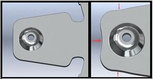
Form quality can be better on a press brake, but it also can suffer. Forming near the edge of a blank may cause drawing (see Figure 3), something that would have been prevented previously by forming before parting or blanking. Also, without the benefit of a large sheet securely held by clamps, unbalanced loads or the presence of lateral forces can displace the blank, despite blank holder use, causing very poor form quality—if forming is possible at all.
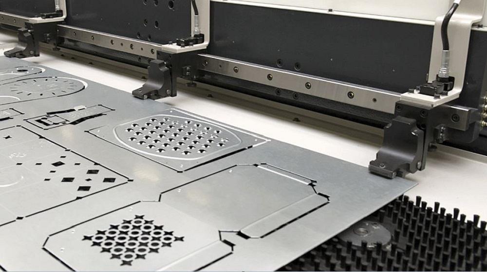
FIGURE 1. Because the sheet is firmly clamped and precisely positioned, a punching machine can deliver form features that are crisp, accurate, and properly located. These parts leave the punching machine nearly complete without requiring an operator to touch them.
When considering forming parts on the brake, it’s also important to acknowledge the possibility that a part produced via another process (stamping or punching) required multiple machine strokes to be successful.
These challenges can be overcome with proper planning and understanding of what can be achieved and at what cost.
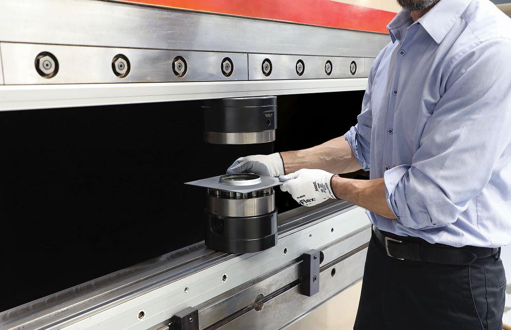
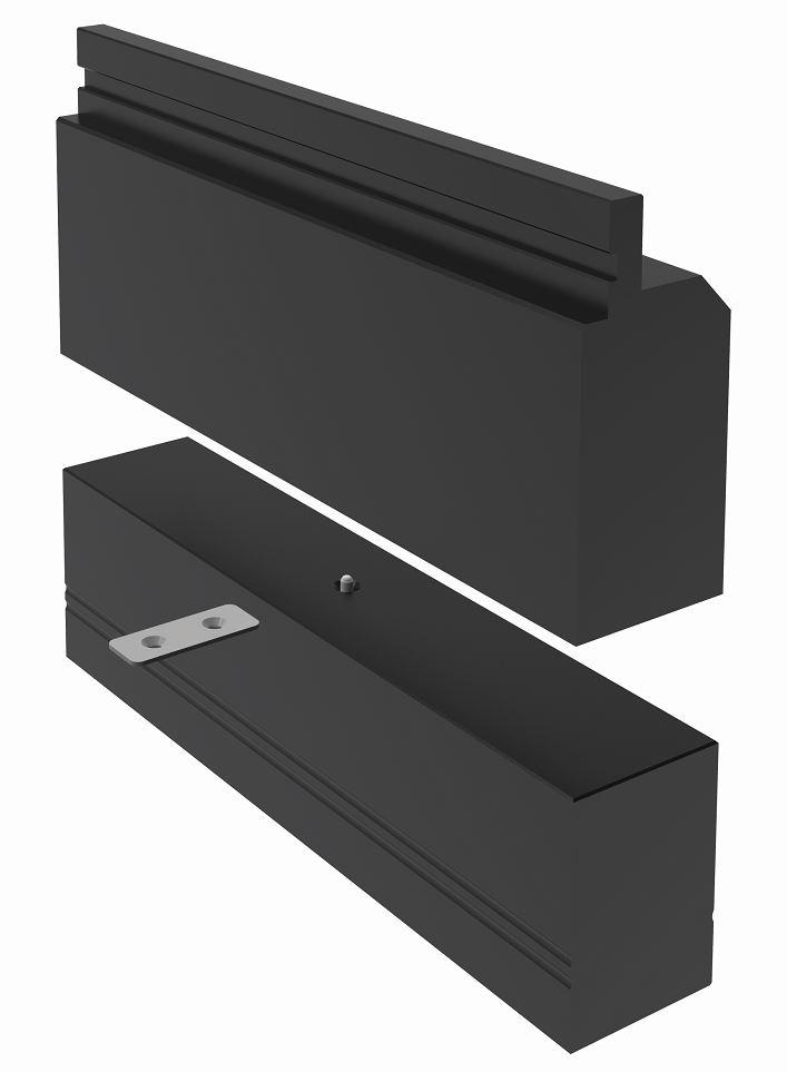
Conventional, precision press brake tooling can be used to create forms in sheet metal blanks in lieu of the punching machine (see Figure 4). As mentioned, not only can it replicate the forms typically created by punch tooling, but it also opens the door to producing forms that are not possible on the punching machine.
A robust punch and die profile allows for greater forming loads. The large, linear, block-shaped footprint provides the option for blank holding mechanisms. Along with that comes the ability to create greater holding force, reducing material draw and distortion. Forming load is distributed across a larger area of the beam, thus reducing the chance of beam damage.
Punching’s decades-long reign as the primary process for creating forms in sheet metal parts has as much to do with the tooling as it does with the machine—possibly more. Innovations in punch tooling, in a variety of cases, have even driven machine innovations. Unlike brake tooling, which sometimes must have a unique size or profile for each application, punch tooling is created for an industry-standard family of sizes. Different machine styles use different tooling styles and sizes, but for the most part, tooling is confined to a handful of footprints. The machine tools and processes have been perfected to produce excellent quality, allowing for short lead times (see Figure 5).
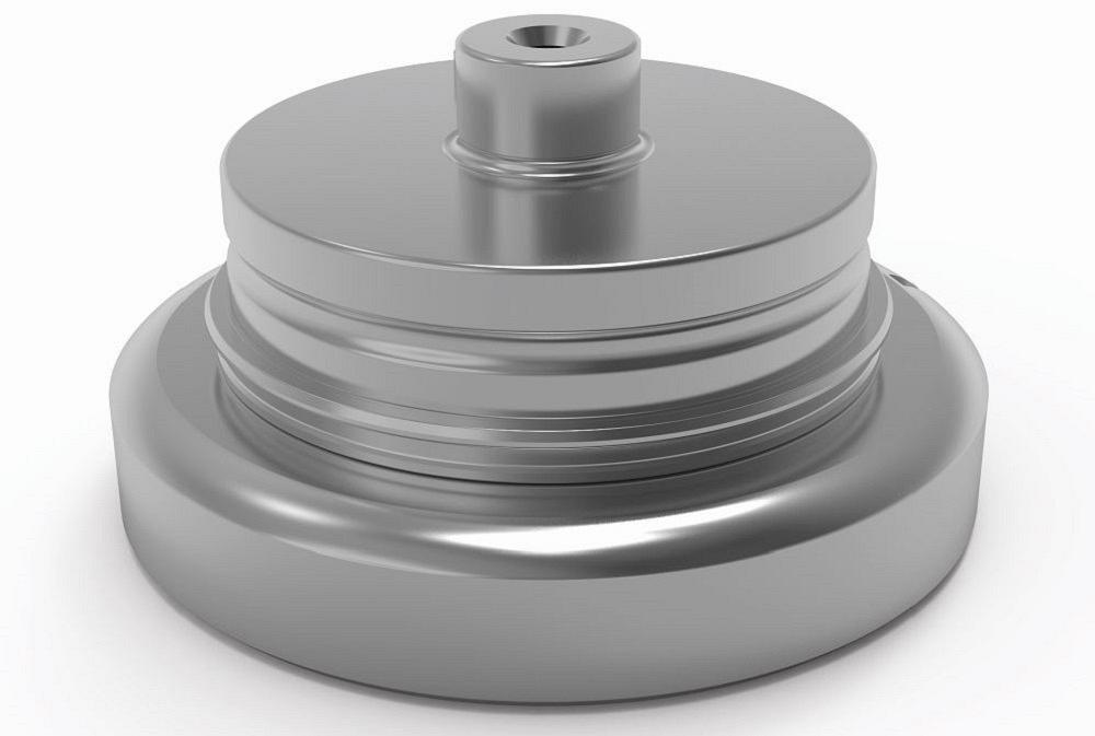
The sheet metal punching and bending worlds differ greatly. Focusing on the tooling, maybe the most obvious differences are physical size, shape, and weight—linear block-shaped versus cylindrical. The larger brake tooling commands a higher cost (and longer lead time) for the increased material mass and machining time.
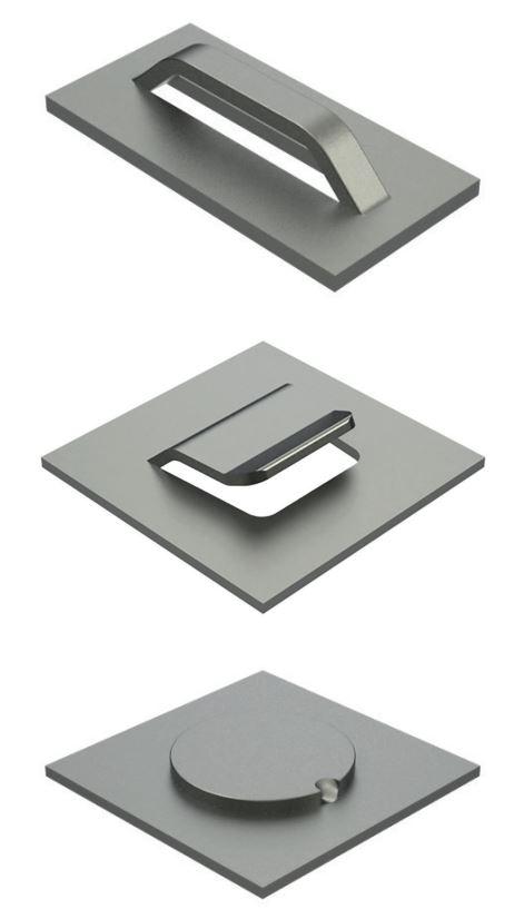
Each tool is generally capable of producing a single result, whether that’s multiple features or a single, per-machine stroke, and usually in one material type and thickness (see Figure 6). Consider a tool from each world, built to produce an emboss or deboss at Ø20 mm with a height of 6 mm. Each tool would produce the same form, but the brake tool would cost much more and take significantly longer to receive. If the form needs to change or a new part requires a slightly different size emboss, new tooling would be required, and cost and lead time would, again, be much greater for the brake tooling than the punch tooling.
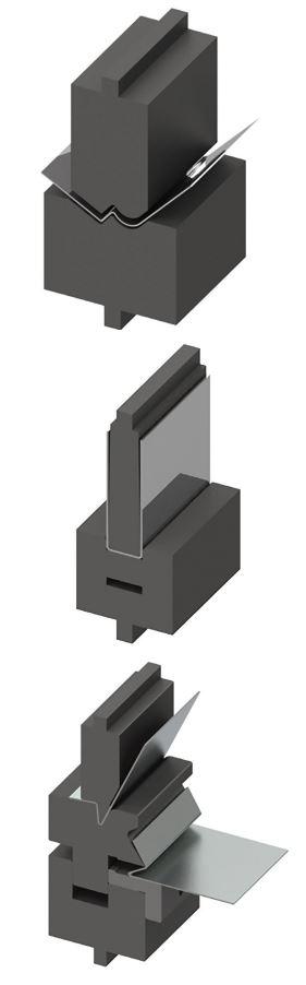
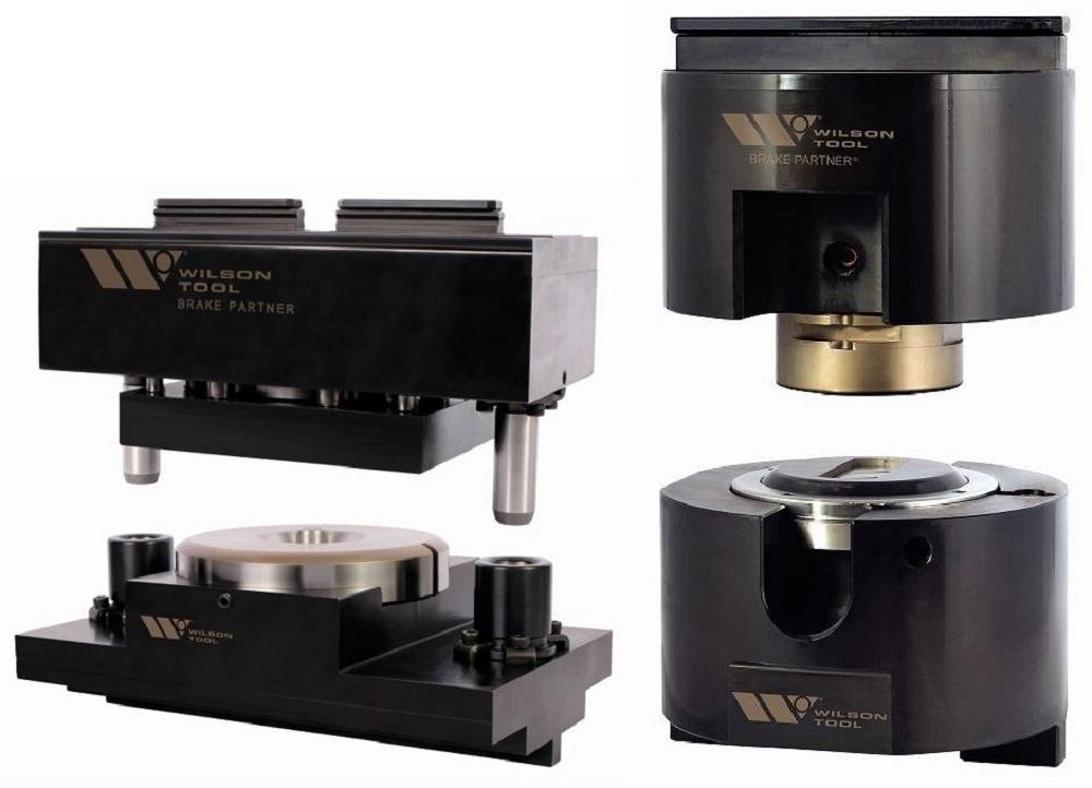
The additional operation of forming on a press brake after laser cutting has been justified, and conventional brake tooling can do the job, but it’s not the best solution. A more unconventional approach is to bring brake and punch tooling together (see Figure 7). Many of the benefits of a press brake tool coupled with the performance of punching tool components make it easier to transition to the brake for forming.
Savvy fabricators have been fixturing punch tooling on their brakes with help from their toolrooms. And one tooling manufacturer, with expertise in designing, engineering, and producing both press brake tooling and punching tooling, has been incorporating precision punching components into a press brake tooling system since 2016.
The Brake Partner system of stock, off-the-shelf holders accept part-specific internal components. This lets the fabricator remove these components and install another set to create a different form. The ability to replace only the internal components keeps cost down.
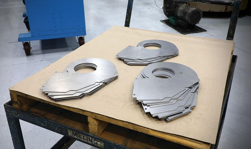
FIGURE 2. These laser-cut blanks are in excellent shape, with no marking and a clean edge. But there’s a significant difference between the state of these parts and the punched parts—these still require the formed features.
The holders are capable of forces of at least double those of most punching machines, and that force is adequately distributed to prevent beam damage. Large embossed logos, coined stamps, dash and ground symbols, and letterstamp tooling are good examples of applications that benefit from this system. The blank holding system can deliver a higher force than punching guide assemblies.
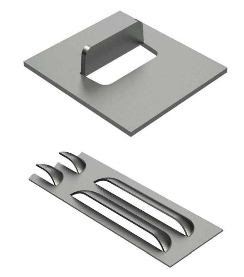
The nonguided holder version, which is manually aligned in the machine, can handle most forming applications such as preslit wipe tools and louvers (see Figure 8).
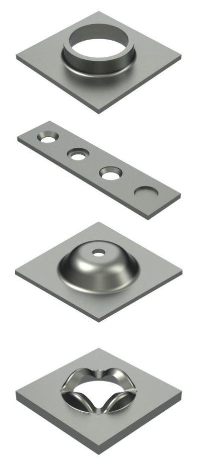
Part-locating features such as locating pins (see Figure 9), machined pockets, adjustable keying blocks, and fingers can be incorporated into the tooling. Extrusions, formed countersinks, embosses with a hole, thread forms/Tinnerman nuts, and tread plates can be positioned by placing the prehole over a replaceable pilot (see Figure 10). For smaller parts or forms that are near the edge of the sheet, a hard stop or a pocket can be machined into the lower die. Various adjustable, detatchable gauges also can be incorporated.
Forms requiring lancing or piercing are better suited for the guided version to ensure that proper alignment and cutting clearance are maintained (see Figure 11). Anytime a slug is produced, as is the case with a cluster pierce tool, additional components are required.
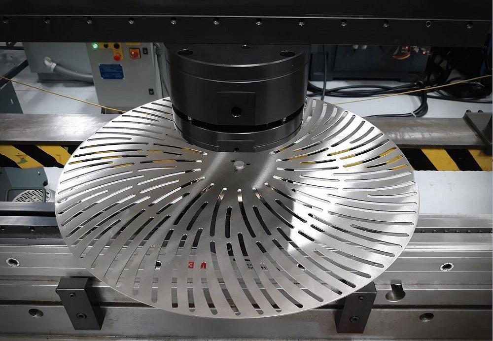
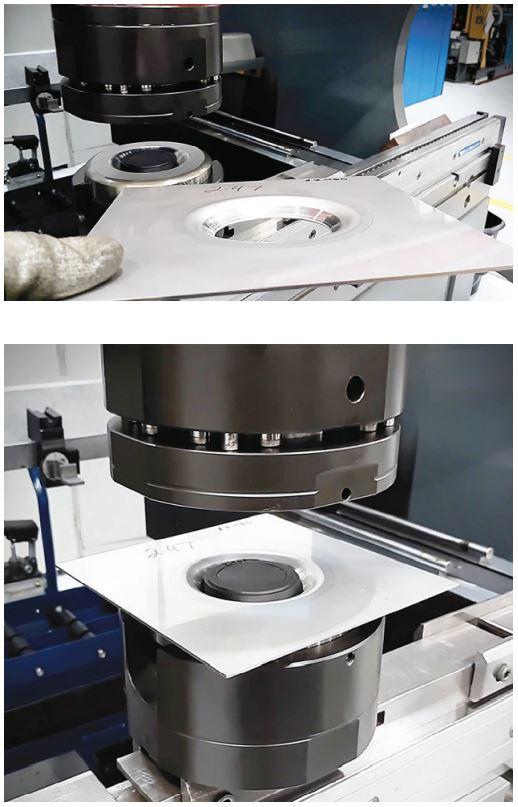
Many fabricators are embracing this new approach to making punch forms, from forming disc-shaped parts, which cannot be held in punch machine clamps, to sink drain forms to piercing holes.
Various gauging methods are in use to address the part-locating challenge created with the switch to the brake. High pressure behind a blank holder or pressure pad keeps parts flatter (see Figure 12).
Whether fabricators are already creating punch forms on the brake or are considering the switch, innovative, unconventional options are available that make it an economically sound, lean, and reliable method for meeting immediate needs and potentially opening the door to new revenue.

The Fabricator is North America's leading magazine for the metal forming and fabricating industry. The magazine delivers the news, technical articles, and case histories that enable fabricators to do their jobs more efficiently. The Fabricator has served the industry since 1970.
start your free subscription
Easily access valuable industry resources now with full access to the digital edition of The Fabricator.

Easily access valuable industry resources now with full access to the digital edition of The Welder.

Easily access valuable industry resources now with full access to the digital edition of The Tube and Pipe Journal.

Easily access valuable industry resources now with full access to the digital edition of The Fabricator en Español.
In this episode of The Fabricator Podcast, Caleb Chamberlain, co-founder and CEO of OSH Cut, discusses his company’s...


