Instead, it got used to break a lot of cutter bits – the learning curve to CNC-ability is strewn with such things, everyone discovers.
Engineer in Wonderland cnc-related blogs are indexed here
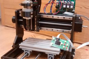
The steam ran out a little as I discovered that using CNC router software is not as straight-forward as 3D printing software (and that is not simple either), and also because it quickly became evident that there is an awful lot of slack and flexibility in the x-axis (side-to-side), and slack including nodding in the z-axis (up-and-down). The y-axis (front-to-back) is pretty good.
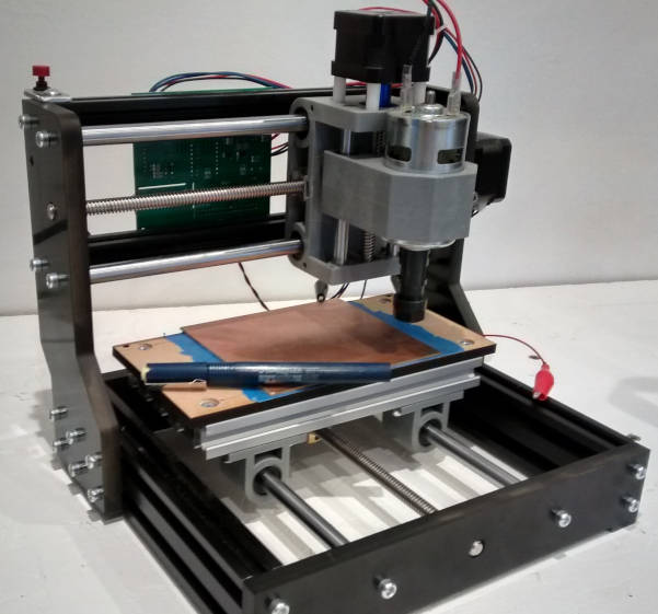
An 1610Pro router is the little brother of the popular 3018 size See more about router sizes here
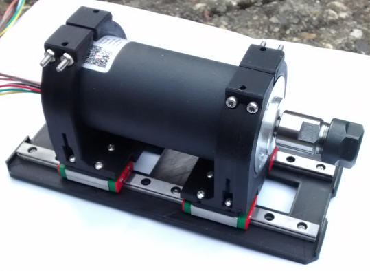
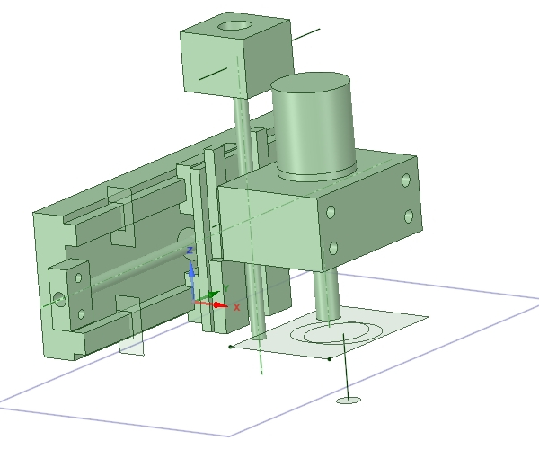
A renewed need to make some pcbs re-ignited interest in the router, so I have had a go at making a z-axis mock-op (above).
At the moment, the rails (so carefully cleaned) are binding unpleasantly once all the screws are tightened.
I am particularly pleased with making the motor-mount in two parts, using the motor as a stressed component, to allow cooling air to get to around motor (and make space for a possible fan).
BTW, this is the very nice Longdaio 250W brushless dc spindle motor, that I bought with control electronics and a psu over a year ago.
Vertical movement is through an 8mm lead screw (not in the photo), with threads printed directly into the plastic (then tapped for precision) of the two mounts. Any backlash that develops can be removed by moving one of the clamps up or down the motor slightly – another cunning feature, I feel.
 Initial idea, now much built-upon
At the moment, the plastic is PLA – which is only good for operation up to about 50°C, but is one of the more rigid printable plastics. Carbon fibre-infused PETg would be more temperature resistant, but only a tiny bit more rigid.
As far as I can calculate, if I make the back support from 10mm thick PLA, it will be as stiff at 3mm aluminium (I am no mechanical engineer, please put me straight in the comments if you know this to be wrong).
Anyway, forces are not high, I just want to get the obvious slop out and make some crisp pcbs.