How to Determine the Currently Active Work Offset Number
Determining the currently active work offset number is practical when the program zero point is changing between workpieces in a production run.
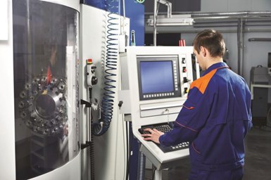
Many of today’s machining centers come with a large quantity of work offsets. FANUC CNCs, for instance, come standard with six sets of work offsets, but they are commonly equipped with at least 48.
Invoking a work offset from within a program is simple. G54 through G59 invoke standard work offsets 1-6. G54.1 P1 through P48 invoke additional work offsets 1-48 — the P-word specifying the work offset number. There may be times when the values in the currently active work offset will need to be determined or modified. This means it will have to be determined which work offset is active from within a given program.
Determining the active work offset may be necessary when the program zero point changes from workpiece to workpiece in a production run due to the nesting method used to locate the workpiece in a fixture. This is a common issue with casting and forgings. A spindle probe might be used to determine the precise program zero location for each workpiece. The currently active work offset may be close (set from the last workpiece), but not precise enough for the next workpiece. The spindle-probing custom macro will not automatically know which work offset has been invoked, yet it must be able to modify its program zero assignment registers for every workpiece being run.
In similar fashion, a spindle probe (or aligning bar) may be used to square up the rotary axis table of a horizontal machining center — or a fixture mounted to the rotary axis — with one of the machine’s linear axes. Once squaring is accomplished, the rotary axis register of the currently active work offset must be modified. If the process is to be automated and universal, the program will have to determine which work offset is currently active.
FANUC system variables are involved with determining the work offset number for the currently active work offset. Which system variable is involved is based upon which work coordinate system set is equipped in the CNC. If the machine has only six work offsets, system variable #4014 returns the numerical value of the currently specified work offset G code (54 through 59). To determine the work offset number, simply subtract 53 from the value of #4014.
If, for instance, G56 is currently instated (work offset 3), the value of #4014 will be 56. Subtracting 53 from 56 renders the work offset number (3).
It gets a little more complicated if the FANUC CNC is equipped with more than six work offsets since personnel could be using G54 through G59 to invoke work offsets 1-6 or G54.1 Pxx to invoke additional work offsets 1-48. The P-word specifies the work offset number. This means it must first be determined which set of work offsets is being used.
System variable #4130 returns the value of the work offset when G54.1 is being used to invoke the work offset. If the current value of #4130 is 0, then G54.1 is not being used. In this case, system variable #4014 can be used to determine the currently active work offset — as previously explained.
On the other hand, if #4130 is greater than 0, G54.1 is being used to invoke the work offset. Again, #4130 will render the work offset number. Consider these commands that can be used to determine which set of work offsets is being used. In either case, local variable #33 will be set to the currently active work offset number.
- .
- .
- IF [#4130 GT 0] GOTO 5 (G54.1 is being used)
- (G54-G59 is being used)
- #33=#4014-53 (work offset number – 1-6)
- GOTO 10
- N5 (G54.1 is being used)
- #33=#4130 (work offset number – 1-48)
- N10 (program continues)
- .
- .
Once a user determines which set of work offsets is being used and the currently active work offset number, they can use the data-setting command (G10) to modify registers in the currently active work offset. With G10, an L-word specifies the kind of data being set. Use L2 to specify that data is to be written into one of the G54-G59 work offsets. Use L20 to specify that data is to be written into one of the extended work offsets (again, specified with G54.1 Pxx).
As a more complete example, say a spindle probe has just measured the program zero location in each linear axis. It has stored program zero assignment values in common variables #111, #112 and #113 for the X-, Y- and Z-axes, respectively. Here are commands that will modify the X-, Y- and Z-axis registers of the currently active work offset for a machine that is equipped with both the standard set of work offsets (G54-G59) and the extended set (G54.1 Pxx).
- .
- .
- IF [#4130 GT 0] GOTO 5 (G54.1 is being used)
- (G54-G59 is being used)
- #33=#4014-53 (work offset number – 1-6)
- G10 L2 P#33 X#111 Y#112 Z#113
- GOTO 10
- N5 (G54.1 is being used)
- #33=#4130 (work offset number – 1-48)
- G10 L20 P33 X#111 Y#112 Z#113
- N10 (program continues)
- .
- .
Related Content
Inside an Amish-Owned Family Machine Shop
Modern Machine Shop took an exclusive behind-the-scenes tour of an Amish-owned machine shop, where advanced machining technologies work alongside old-world traditions.
Read MoreHow to Reduce Cycle Times by 70% and More on Your Existing CNCs and Dramatically Improve Tool Life Too
By employing advanced high efficiency milling techniques for the entire machining routine, SolidCAM’s iMachining technology can drastically reduce cycle times while vastly improving tool life compared to traditional milling.
Read MoreChoosing Your Carbide Grade: A Guide
Without an international standard for designating carbide grades or application ranges, users must rely on relative judgments and background knowledge for success.
Read MoreChoosing The Right Grinding Wheel
Understanding grinding wheel fundamentals will help you choose the right wheel for the job.
Read MoreRead Next
3 Mistakes That Cause CNC Programs to Fail
Despite enhancements to manufacturing technology, there are still issues today that can cause programs to fail. These failures can cause lost time, scrapped parts, damaged machines and even injured operators.
Read MoreThe Cut Scene: The Finer Details of Large-Format Machining
Small details and features can have an outsized impact on large parts, such as Barbco’s collapsible utility drill head.
Read More.jpg;maxWidth=970;quality=90)
.jpg;width=70;height=70;mode=crop)


.jpg;maxWidth=300;quality=90)


.png;maxWidth=300;quality=90)


